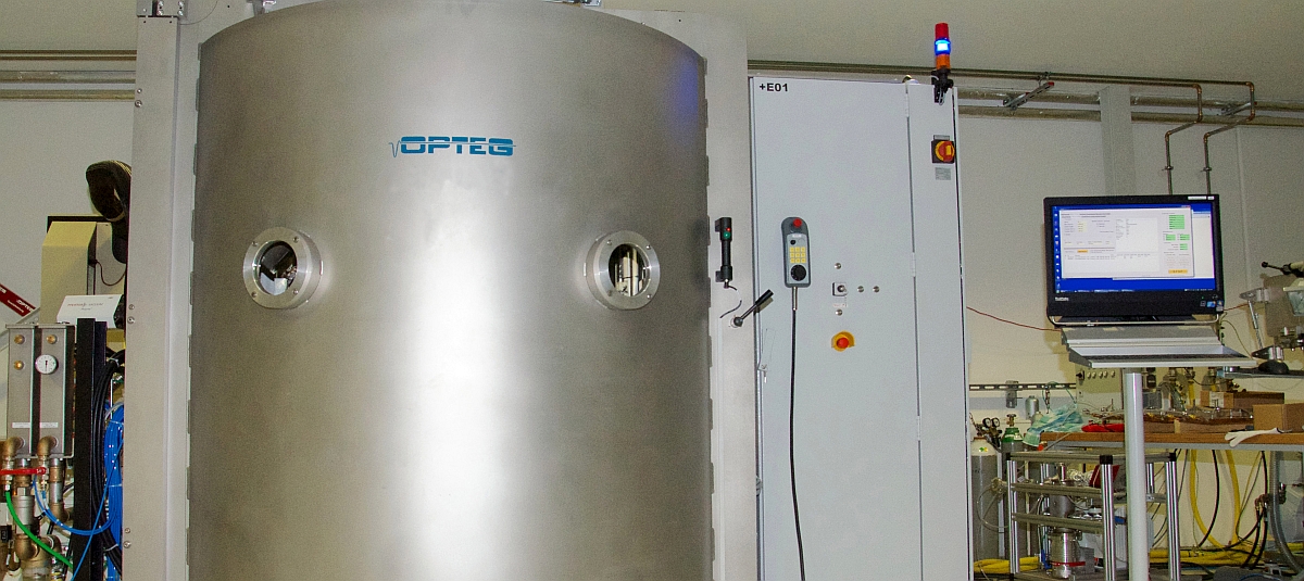
Ion beam figuring with an OMF system
What are the individual steps of the process?
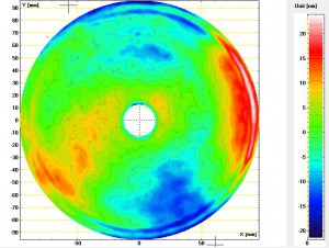 First, the workpiece is thoroughly cleaned. Any remaining dirt particles would have a negative effect on the processing result. After this preparatory work, the process begins with an interferometric measurement of the sample. This involves precisely analyzing the surface, creating a surface profile and determining the exact extent to which certain areas need figuring. A simulation then creates a movement program for the ion source. The program stores information on which position should be covered by the ion beam, and at what speed.
The process and the ion source are stable, although the parameters may change over time. A sample of the same material is used to determine the etching rate and set the source parameters. This determination process for the etching rate is necessary for all ion beam diameter.
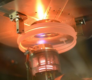
The ion beam figuring process now begins in the OMF system. The load lock in front of the vacuum chamber is opened and the sample placed inside. The load lock is then evacuated and the sample can be locked in the chamber. The interferometric measurement determined the size of the error to be corrected, such as on the surface of an optical lens. The correct beam diameter is then chosen, depending on the size of the error and therefore that of the material to be figured. The diameter of the ion beam source is adjusted using diaphragms set in front of the source, or by using a different beam source. The smaller the size of the error in lateral resolution, the smaller the beam has to be. The process first corrects the longer defects, correcting them with the larger beam diameter and gradually working down to the shorter defects with the smaller ion beam.
 The system currently uses ion beam sources with beam profiles of 40 mm, 20 mm or 8 mm. There are currently diaphragms available for the 8 mm source, although any diaphragms can be used here. The sizes are staged from 0.5 mm, 1 mm, 2 mm, 4 mm, etc., with a diaphragm changer for the 20 mm source also planned. Ion sources with a diameter of 40 mm are also available for larger samples that require a larger area to be covered in a single pass. In the first pass, or in the first use of a diaphragm, the ion source is subjected to a Faraday scan to determine the spatial position of the beam (calibration). This also helps detect any irregularities in the profile of the ion beam. No conclusions on the etching rate are possible with this, however. The system then loads the file containing the movement program determined in the simulation (dwell time file) and the figuring process can begin. Once the program has ended, the sample is then removed and the load lock opened.
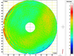
ion beam figuring after measurement
The sample is then subjected to another interferometric measurement. The iterative process that follows gradually improves the surface quality in every pass until the desired quality requirements are met. The finer the level of figuring required on the surfaces, the smaller the diaphragms in front of the ion source need to be.
Figuring without interim measurements
The simulation always determines and displays an expected result, i.e. an initial estimate. Ideally, this estimated result is achieved in the actual process, with only negligible deviations. A well-running machine and good control over the process make it more likely that the final result reflects the initial estimate. It is also possible to use the simulation result and conduct a new simulation to proceed with the next iterative step. This removes the need for the interim measurement described above.
Changing diaphragms on the ion source within the vacuum chamber
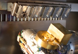
System for changing the diaphragms for the ion beam source
OPTEG engineers developed a system for changing the diaphragms on the ion source within the chamber. This helps further optimize the process and reduce processing time. The system is able to replace an 8 mm diaphragm with a 4 mm diaphragm, for example, without breaking the vacuum.
Even more innovation with live etching rates
Our team of specialists developed a live etching rate device that can be used to determine etching rates without having to process an additional sample of the same material as described above. This removes the need to insert, process, remove and measure a dummy sample to determine the etching rate. The innovative add-on module can perform this task inside the vacuum chamber, comparable to a Faraday scan. This significantly reduces the preparation time.
The following 3-minute video illustrates the process of ion beam etching